Skincare
3 Ways to Test a Relay
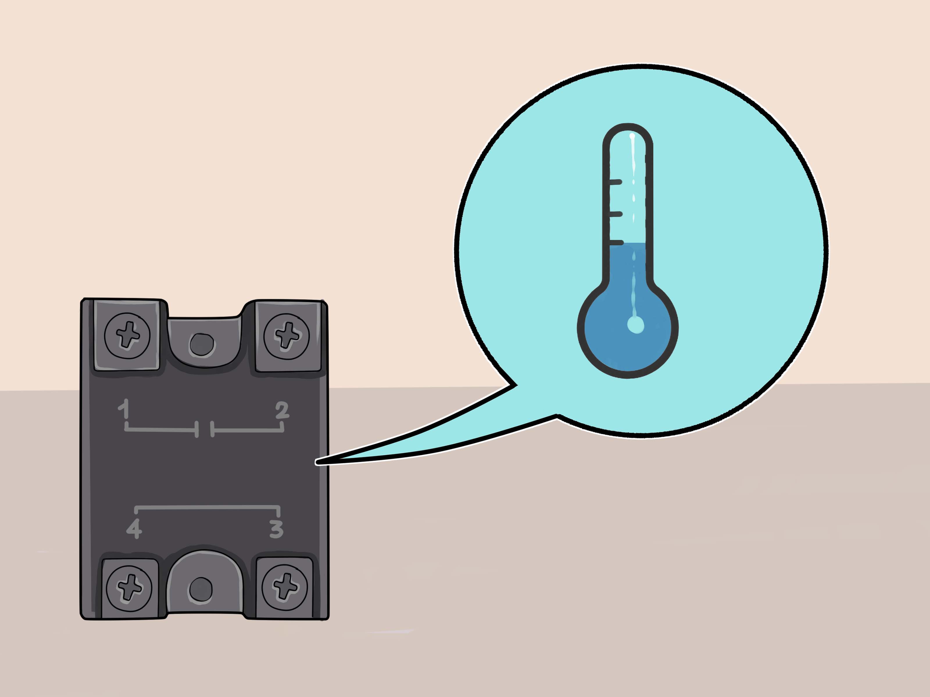
Jun
A relay is a tiny electrical gatekeeper with an important job: it lets a low-current circuit control a higher-current device. In a car, a relay may switch on the fuel pump, cooling fan, horn, headlights, starter circuit, or A/C compressor clutch. In appliances, relays help start compressors, motors, heaters, and control boards. In electronics projects, they let microcontrollers boss around loads that would otherwise laugh at their tiny output pins.
When a relay works, nobody throws it a party. When it fails, suddenly the horn is silent, the fan refuses to spin, the refrigerator acts moody, or your DIY project behaves like it drank three espressos and forgot the assignment. The good news? You can test many common electromechanical relays with basic tools, a little patience, and a healthy respect for electricity.
This guide explains 3 ways to test a relay: a quick inspection and swap test, a multimeter resistance and continuity test, and a bench activation or load test. We will focus on common automotive-style and general-purpose electromechanical relays, but the same logic applies to many appliance and hobby relays. Solid-state relays are different animals, so do not expect them to click, clack, or behave exactly like mechanical relays.
Before You Start: Know What a Relay Actually Does
Most electromechanical relays have two sides: the coil side and the contact side. The coil is an electromagnet. When voltage is applied to the coil, it pulls an internal armature and changes the position of the contacts. The contacts are the switching side of the relay. They either open or close the circuit connected to the load.
On a typical automotive relay, terminals are often labeled like this:
- 85 and 86: Coil terminals. These energize the relay.
- 30: Common power terminal.
- 87: Normally open contact. It connects to terminal 30 when the relay is energized.
- 87a: Normally closed contact. It connects to terminal 30 when the relay is not energized.
A four-pin relay usually has terminals 85, 86, 30, and 87. A five-pin relay usually adds 87a. Other relays may use different numbering or a printed diagram, so always check the case, wiring diagram, service manual, or datasheet before applying power. Guessing terminal numbers is a wonderful way to turn a cheap relay into a tiny smoke machine.
Tools You May Need
- Digital multimeter with resistance and continuity settings
- 12-volt battery or regulated power supply for automotive relays
- Fused jumper wires or test leads
- Needle-nose pliers or relay puller
- Wiring diagram or relay pinout
- Safety glasses and insulated gloves when appropriate
Safety matters. For low-voltage automotive relay testing, a fused jumper wire is strongly recommended. For household appliances or line-voltage equipment, unplug the device before removing parts. If the circuit involves 120 volts, 240 volts, HVAC equipment, industrial panels, or anything you do not fully understand, call a qualified technician. Electricity is helpful, but it has terrible manners when mishandled.
Way 1: Do a Visual, Sound, and Swap Test
When to Use This Method
This is the fastest relay test and a good first step when troubleshooting cars, motorcycles, lawn equipment, appliances, or simple control circuits. It does not prove everything, but it can quickly reveal obvious failures. Think of it as asking the relay, “Are you obviously dead?” before bringing out the full detective kit.
Step 1: Inspect the Relay and Socket
Remove the relay only after turning off the circuit and disconnecting power where needed. Look at the relay body and terminals. Burn marks, melted plastic, corrosion, loose pins, or a burnt smell are strong clues that something has gone wrong. Also inspect the relay socket. A perfectly good relay can fail to operate if the socket terminals are loose, green with corrosion, overheated, or pushed back in the connector.
Do not overlook heat damage. Relays that switch high-current loads can develop pitted or welded contacts over time. If the relay case looks warped or smells like toasted electronics, replacement is usually smarter than heroic testing.
Step 2: Listen and Feel for a Click
In many circuits, you can feel or hear the relay click when the controlled device is switched on. For example, turn the ignition key or activate the horn while touching the relay lightly. A working electromechanical relay often gives a small click as the coil energizes and the contacts move.
A click is useful, but it is not a full pass. A relay can click and still have burned contacts that do not carry current properly. That is like a waiter saying “I got it” and then never bringing the fries. The movement happened; the useful work did not.
Step 3: Swap With a Matching Relay
If the relay is in a car fuse box, look for another relay with the same part number, terminal layout, and rating. Swap it into the suspect position. If the problem moves or disappears, the original relay is likely faulty.
Be careful: matching the physical shape is not enough. Confirm the pinout and ratings. A relay that fits the socket may not be electrically identical. Swapping a fuel pump relay with a matching horn relay can be a smart test. Swapping random relays because they “look about right” is electrical roulette.
What This Test Tells You
The visual, sound, and swap test can identify obvious relay failure, socket problems, and intermittent issues. It is quick, practical, and beginner-friendly. However, it cannot measure coil resistance, contact resistance, or voltage drop. If the relay passes this quick check but the circuit still misbehaves, move on to a multimeter test.
Way 2: Test Relay Resistance and Continuity With a Multimeter
When to Use This Method
This is the most common and reliable DIY relay test. It checks whether the coil is electrically intact and whether the contacts behave correctly when the relay is at rest. For many automotive and appliance relays, a multimeter gives you the evidence you need before buying a replacement.
Step 1: Identify the Coil Terminals
Find the relay diagram. On many automotive relays, the coil terminals are 85 and 86. On other relays, they may be marked A1 and A2 or shown as a coil symbol. Do not assume; confirm.
Set your multimeter to the ohms setting. Touch one probe to each coil terminal. A healthy coil should show a measurable resistance. On many 12-volt automotive relays, coil resistance is commonly somewhere around tens of ohms to a little over one hundred ohms, but the correct value depends on the relay design. If the meter reads OL or infinite resistance, the coil is open. If it reads extremely close to zero ohms, the coil may be shorted.
Step 2: Test the Normally Open Contact
Set the multimeter to continuity mode. On a typical four-pin automotive relay, check between terminals 30 and 87 while the relay is not energized. The normally open contact should not have continuity at rest. Your meter should not beep.
If the meter beeps between 30 and 87 when the relay is not energized, the contacts may be stuck closed or welded. That is bad news, especially in circuits where the load must turn off. A welded relay can keep a fan, pump, or compressor running when it should stop.
Step 3: Test the Normally Closed Contact
If you have a five-pin relay with terminal 87a, check between terminals 30 and 87a while the relay is not energized. This normally closed path should have continuity at rest. Your meter should beep or show very low resistance.
If terminal 30 and 87a do not have continuity at rest, the normally closed contact may be damaged, dirty, or mechanically stuck. Some circuits rely on 87a for default operation, so a failed normally closed contact can cause confusing symptoms.
Step 4: Understand the Results
Here is a simple interpretation table:
| Test Result | Likely Meaning |
|---|---|
| Coil reads OL or infinite resistance | Open coil; relay will not energize |
| Coil reads nearly 0 ohms | Possible shorted coil |
| NO contact has continuity at rest | Contacts may be stuck or welded closed |
| NC contact has no continuity at rest | Normally closed contact may be damaged |
| Readings change when wires are wiggled | Possible intermittent internal connection or bad socket |
One important warning: a relay can pass a basic continuity test and still fail under load. Contacts may look fine to a multimeter but drop too much voltage when carrying real current. That is why the third method matters.
Way 3: Bench Test the Relay Under Power
When to Use This Method
A bench test energizes the relay coil and verifies that the contacts switch as expected. This is the “show me, don’t just beep at me” test. It is especially useful for automotive relays, accessory relays, and general-purpose DC relays.
Step 1: Prepare a Safe Power Source
For a 12-volt automotive relay, use a 12-volt battery or regulated 12-volt DC power supply. Use fused jumper wires so a mistake does not instantly become dramatic. If the relay has a diode across the coil, polarity matters. The relay diagram may show a diode symbol. In that case, connect positive and negative exactly as specified.
If the relay uses AC coil voltage or a higher DC voltage, use the exact rated coil voltage. Do not feed 12 volts into a 5-volt relay and act surprised when it gets spicy. Do not feed 120 volts into anything unless you are trained and using proper safety equipment.
Step 2: Energize the Coil
Connect power to the coil terminals. On a common automotive relay, that usually means battery positive to terminal 86 and battery negative to terminal 85, unless the diagram says otherwise. When power is applied, the relay should click.
No click can mean a bad coil, wrong voltage, wrong terminal identification, bad jumper lead, poor connection, or incorrect polarity on a diode-protected relay. Before declaring the relay dead, verify the test setup. Many innocent relays have been falsely accused by tired humans holding the probes on the wrong pins.
Step 3: Check Contact Switching
While the coil is energized, use your multimeter to check continuity between terminal 30 and terminal 87. The normally open contact should now close. Your meter should beep or show very low resistance.
If the relay has terminal 87a, check terminal 30 to 87a while energized. The normally closed contact should open. In other words, the relay should move the common terminal away from 87a and toward 87.
Step 4: Test With a Realistic Load
For a stronger test, connect a safe test load such as a small 12-volt bulb or suitable resistor through the relay contacts. Energize the coil and see whether the relay actually powers the load. This helps reveal contacts that pass a no-load continuity check but fail when current flows.
In automotive diagnostics, you may also measure voltage drop across the relay contacts while the circuit is operating. A good closed contact should drop very little voltage. A higher-than-expected voltage drop suggests resistance from burned contacts, corrosion, weak socket tension, or wiring issues. If a relay clicks but the fuel pump, fan, or horn receives weak power, contact resistance may be the villain wearing a tiny plastic disguise.
Common Symptoms of a Bad Relay
Relay failure symptoms vary by system, but common clues include:
- A component works intermittently
- A device clicks but does not turn on
- A motor, pump, fan, or compressor will not start
- A load stays on after it should turn off
- The relay buzzes, chatters, or gets unusually hot
- The relay socket shows melted plastic or darkened terminals
- Replacing or tapping the relay temporarily changes the problem
Remember that a bad relay is not always the root cause. A failing motor can draw too much current and damage relay contacts. A loose socket can overheat the relay. Low system voltage can cause relay chatter. A blown fuse, damaged ground, or broken control signal can make a good relay look guilty. Good troubleshooting means testing the circuit, not just tossing parts at it and hoping the electrical gremlin gets bored.
Relay Testing Examples
Example 1: Car Horn Does Not Work
Suppose the horn is silent. First, check the fuse. Then find the horn relay. Press the horn button while touching the relay. If it clicks, the control side may be working, but the contact side, horn, wiring, or ground may be faulty. Swap the relay with a matching one. If the horn returns, the relay was likely bad. If not, use a multimeter to check for power at the horn when the relay is activated.
Example 2: Cooling Fan Runs All the Time
If a cooling fan stays on even when it should stop, a relay contact may be welded closed. Remove the relay. If the fan turns off immediately, test the relay contacts. Continuity between terminal 30 and 87 at rest suggests the normally open contacts are stuck closed. Replace the relay and inspect the fan circuit for excessive current draw.
Example 3: Refrigerator Compressor Clicks but Does Not Start
In appliances, a start relay can fail and prevent the compressor from running. The appliance may click, hum, or stop cooling. Always unplug the appliance before accessing internal parts. Remove the start relay and test for continuity according to the service information for that model. If the relay smells burnt, rattles unusually, or fails continuity checks, replacement may be required. Because refrigerator compressor circuits may also involve capacitors and line voltage, do not go beyond your skill level.
Mistakes to Avoid When Testing a Relay
Using the Wrong Voltage
A relay coil is designed for a specific voltage. A 5-volt relay, 12-volt relay, 24-volt relay, and 120-volt relay are not interchangeable just because they all have little boxes and terminals. Overvoltage can burn the coil. Undervoltage can cause weak operation or chatter.
Ignoring the Relay Diagram
Terminal layouts vary. Some relays have built-in resistors or diodes. Some have multiple poles. Some have special contact arrangements. Always read the markings before testing.
Trusting the Click Too Much
A click means the coil moved something. It does not prove the contacts can carry current. If the circuit still fails, test the contact side under load.
Testing in a Powered Circuit Without Understanding It
Resistance and continuity tests should normally be done with the component removed and power disconnected. Measuring resistance in a live circuit can damage the meter or the circuit. It can also provide nonsense readings, which are less helpful than a fortune cookie and slightly more expensive.
When Should You Replace the Relay?
Replace the relay if the coil is open or shorted, the contacts are welded, the case is melted, the terminals are badly burned, or the relay fails to switch reliably during bench testing. Also replace it if it passes one test but repeatedly fails in actual use, especially when heat or vibration is involved.
However, if the replacement relay fails again quickly, stop and investigate the circuit. Something may be overloading the relay, such as a seized fan motor, failing pump, shorted wiring, poor ground, or incorrect fuse size. A relay is often the messenger. Do not blame the messenger until you check who sent the bad news.
Extra Field Experience: Practical Lessons From Testing Relays
Relay testing becomes much easier after you have seen a few real-world failures. One of the most common lessons is that relays often fail in boring ways. They do not always explode, smoke, or announce their retirement with sparks. Sometimes they simply become intermittent. A car may start perfectly in the morning, refuse to start at lunch, then behave normally by dinner. That kind of problem can make a person question their tools, their memory, and possibly the laws of physics.
Heat is a frequent troublemaker. A relay may work when cold but fail after the engine bay warms up. Internal coil windings can open as temperature rises, or worn contacts may become unreliable under load. If you suspect a heat-related failure, test the relay when the symptom is present. A relay that passes on the workbench at room temperature may still fail in the vehicle after twenty minutes of driving. That is why technicians often compare readings between a suspect relay and a known-good relay of the same type.
Another practical tip is to label everything before removing multiple relays. Fuse boxes can contain several identical-looking relays. Once they are scattered on the bench, they all look like tiny black mystery cubes. Take a photo before removal. Mark the suspect relay with tape. Keep track of which relay came from which socket. Future you will appreciate this more than present you expects.
Socket tension is another sneaky issue. A relay may test perfectly outside the vehicle, but the circuit still fails because the socket terminals do not grip the relay pins tightly. Loose terminals create resistance, heat, and intermittent operation. If a relay wiggles too easily or the terminals look spread apart, the socket may need repair. In high-current circuits, poor socket contact can melt plastic around the relay base. When you see melting, do not just replace the relay and move on. Repair the connector and inspect the load.
Corrosion is equally annoying. Moisture inside engine compartments, outdoor equipment, trailers, boats, and HVAC units can oxidize terminals. A thin layer of corrosion can stop a low-current control signal or weaken a high-current load path. Cleaning terminals may temporarily help, but badly corroded connectors should be replaced. Electrical contact cleaner and a small brush can be useful, but aggressive scraping may remove plating and make corrosion return faster.
One of the best habits is to test both sides of the relay circuit. Beginners often focus only on the relay itself. Professionals ask four questions: Is the relay receiving coil power? Does it have a proper coil ground? Is power available at the common contact? Does power leave the switched contact when the relay energizes? That simple sequence can separate a bad relay from a bad fuse, control module, ground, switch, or load.
For example, imagine a fuel pump relay that does not click. The relay may be bad, but it may also be missing the control signal from the computer, lacking ignition power, or sitting in a socket with a broken ground. If you replace the relay without checking those inputs, you may spend money and learn nothing except the return policy at the parts store.
In electronics projects, relay modules introduce another lesson: the relay may be fine, while the driver circuit is not. A microcontroller pin usually cannot power a relay coil directly. Relay boards often include a transistor, diode, optocoupler, or indicator LED. If the relay does not activate, check the module power supply, ground connection, trigger logic, and jumper settings. Some modules are active-low, meaning they switch on when the control input is pulled low. That little detail has fooled many builders into thinking their relay was defective when it was simply waiting for the opposite signal.
Finally, never underestimate the value of a fused jumper wire. It can save wiring, tools, and dignity. When bench testing automotive relays, a small inline fuse limits the drama if you accidentally touch the wrong terminals. A relay test should end with information, not melted insulation and a new appreciation for emergency purchases.
Conclusion
Testing a relay is not magic. It is a simple process of checking the coil, checking the contacts, and confirming the relay can switch power under real conditions. Start with the quick visual, click, and swap test. Then use a multimeter to measure coil resistance and contact continuity. Finally, bench test the relay with the correct voltage and, when appropriate, a safe test load.
The main keyword here is how to test a relay, but the real goal is understanding the circuit. A relay is only one part of the system. If the relay fails, ask why. If the relay passes, keep troubleshooting. With a meter, a diagram, and a calm approach, you can turn electrical confusion into a clean diagnosisand maybe even enjoy the tiny click of victory.
